- About us

- Products

- R&D

- Service

- Contact us


+86-510-87189500
+86-510-87189500
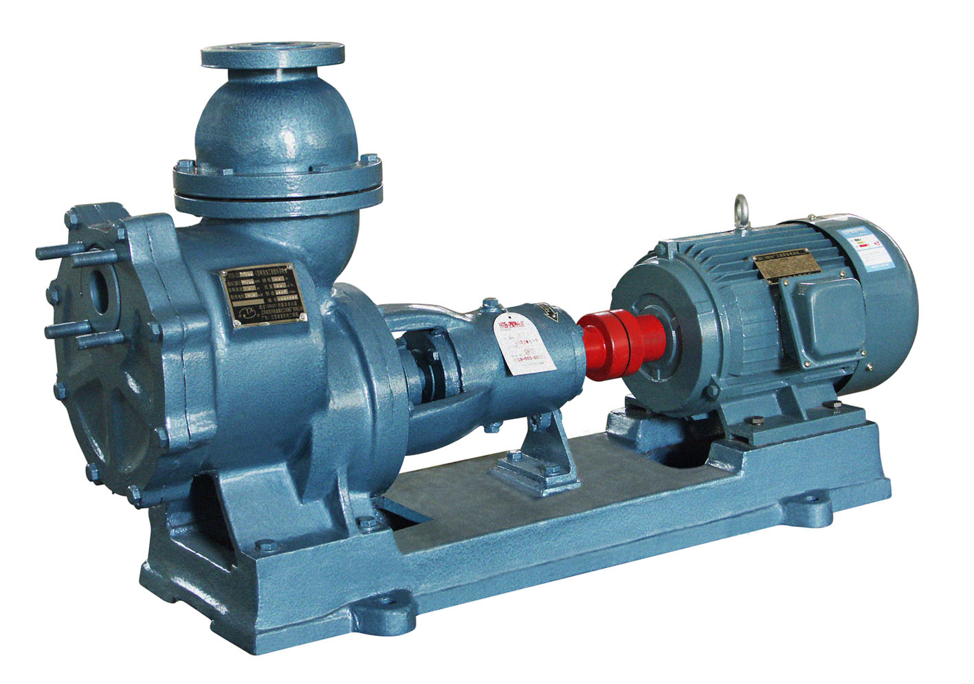
1. Overview
The HTB-ZX□/□-U series of corrosion-resistant engineering plastics self-suction pumps are horizontal single-stage single-suction suspended self-suction pumps. They are carefully designed based on the advanced technology of similar products at home and abroad, adopting a unique "siphon+vacuum pump principle". The flow parts are made of steel-lined ultra-high molecular weight polyethylene through integral mold pressing, which has excellent corrosion resistance and wear resistance, suitable for conveying clear liquid or corrosive media containing a small amount of particles.
Compared with other self-suction pumps, this pump has the following significant advantages:
★The pump adopts a unique "siphon+vacuum pump principle" to complete the self-suction process, with excellent self-suction performance. It does not require the installation of buffer valves and air control valves, and there is no backflow hole in traditional self-suction pumps, so there is no phenomenon that affects self-suction performance due to the blockage of the backflow hole; it truly achieves "one-time drainage, lifelong self-suction".
★The pump adopts a horizontal suspended rear-drawn structure, and the pump body is composed of three rooms: the liquid storage room, the vortex room, and the air-water separation room. The overall lining mold pressing is characterized by a novel, compact, and beautiful structure, convenient maintenance, reliable operation, and durable.
★The pump also adopts the newly developed Y4 type of our company's integrated hard-to-hard mechanical seal. This seal is not only more reliable and longer-lasting but also, since it adopts an integrated closed cooling structure, it does not produce acid mist like ordinary mechanical seals during operation, protecting the environment from corrosion. The pump is especially suitable for working positions with particulate corrosive media.
★The pump can be equipped with a liquid level control device to achieve automatic control, without the need for a dedicated person to operate, and it is very convenient to use.
2. Application
The pump is mainly used in various chemical industries, non-ferrous metal smelting (gold, silver, copper, aluminum, zinc, cobalt, nickel, etc.), black metal (steel pickling, manganese industry), chemical fiber, titanium white, rare earth, rare metal, pesticide, phosphatic fertilizer, citric acid, inorganic salt, paper making, desulfurization environmental protection, sewage treatment, etc. The general operating temperature is ≤80℃. If other heat-resistant materials are used, the applicable temperature can reach 120℃. It is the equipment for conveying clear liquid or corrosive media containing a small amount of particles (solid content ≤15%). It is an ideal equipment to replace long-axis liquid-underground pumps, submersible pumps, submersible sewage pumps, etc.
3, Model Description

4, Performance Parameters
| Parameter Model | impeller specifications | Rated speed 2900 rpm | Import×Export mm | Complete machine weight kg | |||||
| Flow rate m3/h | Range m | Matching power kW | Self-suction; height m | Self-suction time s/m | NPSH margin m | ||||
| HTB-ZX4.0/20-U | Standard | 5 | 24 | 3 | 4 | 50 | 4 | 40×40 | 120 |
| 10 | 20 | ||||||||
| 15 | 16 | ||||||||
| HTB-ZX5.0/32-U | Standard | 20 | 33 | 7.5 | 4 | 50 | 4 | 50×50 | 200 |
| 25 | 32 | ||||||||
| 30 | 28 | ||||||||
| A | 20 | 30 | 5.5 | ||||||
| B | 25 | 25 | 5.5 | ||||||
| C | 23 | 20 | 5.5 | ||||||
| HTB-ZX6.5/50-U | Standard | 25 | 52 | 15 | 4 | 50 | 4.5 | 65×65 | 330 |
| 30 | 50 | ||||||||
| 40 | 45 | ||||||||
| HTB-ZX8.0/30-U | Standard | 30 | 33 | 11 | 4 | 50 | 4.5 | 80×80 | 330 |
| 40 | 30 | ||||||||
| 50 | 28 | ||||||||
| HTB-ZX10.0/35-U | Standard | 50 | 37 | 18.5 | 4 | 50 | 4.5 | 100×100 | 400 |
| 60 | 35 | ||||||||
| 70 | 31 | ||||||||
| HTB-ZX10.0/50-U | Standard | 80 | 52 | 37 | 4 | 50 | 5 | 100×100 | 500 |
| 100 | 50 | ||||||||
| 120 | 47 | ||||||||
| A | 80 | 42 | 30 | ||||||
| 100 | 40 | ||||||||
| 120 | 38 | ||||||||
5, Sealing Form

6, Structural Description
.png "1533516835680031.png")
7, Appearance and Installation Dimensions

HTB-ZX□/□-U-shaped Corrosion-resistant Engineering Plastic Self-priming Pump Appearance and Installation Dimensions
| Model | Power KW | Matching motor | Installation dimensions | |||||||||||||||||
| d1 | d2 | D1 | D2 | D3 | B1 | B2 | n1-n1 | n2-n2 | n3-n3 | L0 | L1 | L2 | L3 | L4 | L | |||||
| HTB-ZX4.0/20-U | 3 | Y100L-2 | 40 | 40 | 110 | 110 | 150 | 280 | 280 | 4-M16 | 4-M16 | 4-φ20 | 352 | 244 | 197 | 155 | 490 | 155 | 227 | 989 |
| HTB-ZX5.0/32-U | 7.5 | Y132S2-2 | 50 | 50 | 125 | 125 | 165 | 340 | 340 | 4-M16 | 4-M16 | 4-φ20 | 392 | 258 | 231 | 160 | 645 | 160 | 250 | 1196 |
| HTB-ZX6.5/50-U | 15 | Y160M2-2 | 65 | 65 | 145 | 145 | 185 | 420 | 420 | 4-M16 | 4-M16 | 4-φ23 | 500 | 340 | 243 | 210 | 815 | 210 | 270 | 1409 |
| HTB-ZX8.0/30-U | 11 | Y160M1-2 | 80 | 80 | 160 | 160 | 200 | 420 | 420 | 8-M16 | 8-M16 | 4-φ23 | 490 | 380 | 243 | 210 | 815 | 210 | 270 | 1409 |
| HTB-ZX10.0/35-U | 18.5 | Y160L-2 | 100 | 100 | 180 | 180 | 220 | 460 | 460 | 8-M16 | 8-M16 | 4-φ23 | 530 | 410 | 277 | 210 | 845 | 210 | 277 | 1509 |
| HTB-ZX10.0/50-U | 37 | Y200L2-2 | 100 | 100 | 180 | 180 | 220 | 480 | 480 | 8-M16 | 8-M16 | 4-φ23 | 530 | 482 | 390 | 245 | 855 | 245 | 422 | 1719 |
8, Instructions for Use
(1) Transportation and Installation:
1. When moving, the pump base should be the lifting force point to avoid vibration and impact.
2. The foundation should be solid and level, the pump inlet should be lower than the liquid source level, and as close to the liquid source as possible.
3. The filter screen with a filtering area more than 3 to 4 times the cross-sectional area of the pipeline must be installed at the bottom of the pump's liquid inlet pipe to prevent large particles or debris from entering the pump body and damaging the impeller or affecting the pump's operation; the diameter of the inlet pipe must not exceed the specified requirements, the inlet pipe should be as straight as possible, with no more than 2 elbows, and the total length of the inlet pipe should not exceed 6m, and it should be as short as possible under the condition of meeting the requirements.
4. The pump's outlet pipeline generally does not need to be equipped with a check valve, but if it is, a vent hole must be set at the lower end of the check valve, and a control valve must be installed in the outlet pipeline to prevent the pump from working due to excessive flow; a straight pipe section of more than 1m should also be installed, and it is strictly forbidden to directly install an elbow; the diameter of the outlet pipe must not be less than the specified requirements, and it should be as large as possible in principle, and the total length of the outlet pipe must be more than 1.5 times the total length of the inlet pipe, and it should be as long as possible in principle.
5. When the self-priming pump is used to transport heavy, high-lift, and high静 pressure in the outlet pipeline system, in order to speed up the self-priming speed and shorten the self-priming time, and at the same time, to prevent the mechanical seal from being damaged due to excessive pressure after the machine is stopped, a check valve and a return pipe connected to the material pool must be installed above the height of 1m on the upper part of the flow control valve at the pump outlet, and the control valve is installed on the return pipe, and the control valve on the return pipe is opened at the same time before the pump is started, and the control valve on the return pipe is closed after the return pipe is normally discharging liquid.
6. The pump's inlet and outlet pipelines should have their own supports, and it is not allowed for the weight of the pipeline to be directly borne by the pump to avoid crushing the pump.
7. During installation, do not let screws, nuts, washers, slag, and other debris fall into the pipeline or pump to avoid faults; all parts connected by the inlet and outlet pipelines must be guaranteed to be leak-proof, otherwise, it will affect the self-priming function and the normal operation of the pump.
8, Add 20# lubricating oil to the bearing housing of the pump, to the horizontal center position of the oil level gauge, to prevent the bearings from overheating.
(2)Operating method:
1, Start:
①After the pump is installed, first manually rotate the coupling, it should feel easy and uniform, and pay attention to whether there is any friction sound or foreign object rolling and other noise in the pump. If any, it should be eliminated and the protective cover of the coupling should be installed.
②Connect the power supply, you must first connect and open the mechanical seal cooling water, the water pressure should not exceed 0.1MPa, and then check whether the pump rotates normally in the spot start mode, check whether the motor rotation direction is consistent with the pump rotation direction mark, and do not reverse.
③Loosen the plug of the suction port and fill it with water, and do not use water as a guide when conveying concentrated sulfuric acid, to prevent personal and equipment accidents, and tighten the plug of the suction port after filling it with water.
④Open the inlet valve.
⑤Open the outlet valve by one third (it is necessary to start with the valve open, otherwise the self-priming pump cannot exhaust, and when there is a return pipe at the outlet, the control valve on the return pipe should be opened at the same time), the self-priming pump can be started, and then slowly adjust the outlet valve, so that the pump works in the specified flow range.
⑥Within the specified self-priming height range, if there is no water coming out within 5-8 minutes after the self-priming pump is started, the machine should be stopped immediately to check the cause, to prevent the medium in the pump cavity from heating up and damaging the pump.
2, Operation:
①It is necessary to regularly check whether the mechanical seal cooling water is interrupted, and if it is interrupted, the machine must be stopped.
②It is necessary to regularly check the temperature rise of the pump and the motor, the temperature rise of the bearings should not be greater than 50℃ higher than the room temperature, and its maximum temperature should not exceed 80℃.
③Pay attention to the change of the oil level in the bearing housing, often control it within the specified range, in order to keep the oil clean and well lubricated, it is necessary to replace the lubricating oil regularly. The first time to change the oil is 300 hours, and then every 3000 hours.
④During operation, if any abnormal noise or other faults are detected, the pump should be immediately stopped for inspection, and it can only continue to operate after the fault has been eliminated.
⑤It is strictly prohibited to regulate the flow using the valves on the suction pipe to avoid cavitation.
3. Stopping the Pump:
①Close the discharge valve, then stop the motor.
②Close the suction valve.
③Stop the supply of cooling water to the mechanical seal.
④In cold regions, when the ambient temperature drops below 0℃, the pump should be drained of liquid after stopping to prevent freezing; when transporting liquids that quickly solidify or mortar that is prone to crystallization and precipitation, the pump should also be drained of liquid after stopping to prevent faults during the next startup. After draining, the self-priming pump must be re-filled with water from the suction port before it can be started again.
4. Users can install a minimum liquid level sensor and a maximum liquid level sensor to achieve automatic control, i.e., automatic startup when the liquid level is high and automatic shutdown when the liquid level is low, repeating this process without the need for a dedicated person to monitor it. In this case, the mechanical seal cooling water pipeline must be equipped with a pressure relay that is linked to the pump.
㈢Maintenance Notes:
1. During liquid transportation, the flow rate, head, and self-priming height must be controlled within the specified range, and should not vary greatly, otherwise, the suction chamber may experience a vacuum, causing the pump to fail to operate normally.
2. The self-priming pump is not allowed to produce a vacuum during operation. Once a vacuum occurs, it is necessary to re-fill the pump chamber with water from the suction port before self-priming can occur. Therefore, users must install a device to control the minimum liquid level or assign a dedicated person to monitor it.
3. This self-priming pump cannot transport media that produce a large number of bubbles or gas-liquid mixtures.
4. When transporting media that are prone to crystallization, after stopping the machine, the medium in the pump chamber must be drained from the drainage port and the pump chamber must be flushed to ensure no crystallization medium remains, to prevent damage to the pump during the next startup. When using it again, the pump chamber must be re-filled with water from the suction port before it can be started again.
5. When conveying general non-crystalline media, if the pump is not used for a long time, it is necessary to check whether there is enough liquid in the pump cavity before using it again. If it is insufficient (unscrew the liquid introduction port plug, and there is no medium flowing out of the liquid introduction port), it is necessary to supplement to achieve self-priming.
㈣ Matters needing attention for the use of hard-on-hard mechanical seals:
1. The hard-on-hard mechanical seal can be used for media with a small amount of suspended particles. The moving and static rings of this mechanical seal are both silicon carbide ceramics, so it is very important to keep the cooling water unobstructed and never interrupt the water. Also, prevent sudden changes in temperature and heat from causing cracks in the silicon carbide ceramics.
2. When disassembling the mechanical seal, it should be done carefully and not allowed to be knocked with a hand hammer or iron tools, so as not to damage the sealing surface of the moving and static rings. When installing, it is necessary to check whether all sealing elements are damaged. If there is any damage, it should be repaired or replaced.
3. In the assembly, it is necessary to eliminate the deviation, and the tightening screws should be tightened evenly to avoid the occurrence of bias, which will cause the seal to fail.
4. Adjust the compression of the spring correctly, so that there is no leakage at the seal. Do not over-compress the spring, so as not to damage the moving and static rings.
㈤ Disassembly and assembly:
1. Disassembly: (This pump is of the rear-pull type. If the front cover and pump body are not repaired, there is no need to disassemble the pump body and the inlet and outlet liquid pipes. Just remove the motor foot screws and move the position slightly, then remove the connecting screws between the pump cover and the pump body, and pull out the impeller, pump cover, main shaft, bearing housing, etc. together for maintenance.)
a). Check and close the pump outlet valve, unscrew the plug at the bottom of the pump body, and drain the liquid in the pump.
b). Loosen the oil drain plug below the bearing housing, and drain the lubricating oil in the bearing housing.
c). Remove the coupling guard, and remove the mechanical seal cooling water inlet and outlet pipes.
d). Fix the coupling, turn the shaft in the direction of the impeller rotation, and remove the nut and the impeller lock nut, and remove the impeller together with the moving ring assembly.
e), Then remove the connecting bolts between the pump cover and the bearing housing, and remove the pump cover together with the mechanical seal, then remove the mechanical seal.
f), Use a hydraulic puller or other removal tools to remove the coupling on the main shaft.
g), Remove the front and rear bearing caps on the bearing housing, and remove the main shaft and bearings.
h), Clean all parts, and check for vulnerable parts, overhaul or replace as necessary. When reassembling, all seal O-rings and various seal gaskets should be replaced.
2, Assembly:
a), Clean and wipe all parts, and replace any parts that are cracked, worn, or hardened and deformed.
b), Assemble in the reverse order of the pump disassembly, and the two cooling water connections of the Y4 type mechanical seal should be installed facing up.
c), When installing the mechanical seal, apply a small amount of grease to the polished sealing surface of the moving and static rings, and do not press the cover of the cooling cover tightly, adjust the pressure after the whole machine is assembled.
c), All seal O-rings and various seal gaskets should be in their proper places, not mixed up, and not left out.
d), Pay special attention to the installation of the front cover of the pump, the凸face of the front cover should face the pump cavity, and the plug should be centered with the center of the liquid inlet.
㈥Possible faults and elimination methods:
| Fault; | Reason | Elimination method |
| Can't dispense liquid | 1, Motor direction is incorrect | 1, Change direction; |
| 2, Insufficient traffic flow | 2, Refill the liquid | |
| 3, Suction height is too high or liquid level is too low | 3, Lower the pump level, and start the pump again when the liquid level is high | |
| 4, Inlet pipeline is blocked by debris | 4, Clear blockages | |
| 5, Not enough depth of suction pipe immersion or leakage | 5, Increase the depth of immersion or inspect and repair the seals at the suction end. | |
| 6, Front cover gate or machine seal damaged | 6, Replacement or maintenance | |
| Insufficient traffic | 1, Blade corrosion or wear is serious | 1, Replace the impeller |
| 2, Insufficient speed | 2, Increase the speed of rotation | |
| 3, The suction end has a little leakage of air, affecting the vacuum degree. | 3, Inspection and maintenance of seals at the suction end | |
| 4, The pressure outlet is partially blocked. | 4, Clear the blocked part | |
| Insufficient range | 1, Blade corrosion or wear is serious | 1, Replace the impeller |
| 2, Insufficient speed | 2, Increase the speed of rotation | |
| 3, The suction end has a little leakage of air, affecting the vacuum degree. | 3, Inspection and maintenance of seals at the suction end | |
| 4, The liquid being transported contains gas. | 4, Lower the temperature of the liquid to evolve gas | |
| Power overload | 1, Traffic exceeds the scope of use | 1. Operation of the pump according to its range of use. |
| 2, Medium density is too large | 2, Replace with a higher power motor | |
| 3, Production of mechanical friction | 3, Check the friction parts, adjust or replace the worn parts | |
| Bearing overheating | 1, Pump shaft and motor shaft are not concentric | 1. Adjust concentricity |
| 2, Lack of oil or oil deterioration in the bearing housing | 2. Refuel or change the oil | |
| Noise or vibration | 1, Pump shaft and motor shaft are not concentric | 1. Adjust concentricity |
| 2, The liquid being transported contains gas. | 2, Lower the temperature of the liquid to evolve gas | |
| 3, Rotor imbalance | 3, Replace parts | |
| 4, The nut is loose. | 4, Tighten the nuts of all parts | |
| 5, The pressure outlet is partially blocked. | 5, Clear the blocked part | |
| 6, Bearing damage | 6, Replace bearings | |
| Machine seal cooling water | 1, Mechanical seal damage | 1. Replace or overhaul the mechanical seal. |
| Cloudy | 2, The cover of the mechanical seal cooling is not pressed firmly. | 2, Adjust the mechanical seal cover to the appropriate degree of clamping. |