- About us

- Products

- R&D

- Service

- Contact us


+86-510-87189500
+86-510-87189500
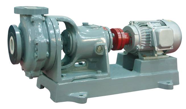
1, Product Introduction
The HTB series corrosion-resistant ceramic pump is a single-stage single-suction cantilever centrifugal pump. The pump body and cover are made of corrosion-resistant, wear-resistant acid-resistant ceramics, with an iron shell armor. The application range is very wide. The pump structure refers to the ISO2858 standard, using the popular rear cover type adjustable bearing housing internationally, with a long bearing spacing, short cantilever, thick shaft diameter, stable, reliable, no noise, oil lubrication cooling, advanced structure, better effect, and a working efficiency 5% to 8% higher than the old domestic models. The structure is compact, easy to maintain, and no need to disassemble the inlet and outlet pipes for inspection. The pump has a high degree of generalization.
2, Performance Summary
Seal: Mechanical seal, packing seal, oil seal seal, dynamic seal.
Applicable medium: Except for hydrogen fluoride and hot concentrated alkali solution, it is a corrosion-resistant, abrasive medium with suspended particles.
Main technical parameters: Use temperature < 100℃, inlet diameter 50mm ~ 200mm,
Flow rate 5 ~ 400m3/h, lift within 50m.
3, Application Range
Non-ferrous metal smelting, non-mineral processing, environmental engineering, sulfuric acid, phosphate, caustic soda, citric acid, water treatment, chemical fiber, electroplating, steel and other industries.
4, Model Description
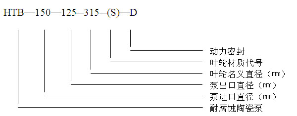
Impeller material code
| Material | Ceramics | Ultra-high molecular weight polyethylene | Modified rubber and plastic | Fluoride alloy | Polyvinylidene fluoride | Polyether chloride | Stainless steel |
Silicon carbide |
||
| Corrosion resistance and wear resistance | Heat and wear resistant | Corrosion resistance | ||||||||
| Code name | Not marked | S | S1 | S3 | S2 | S4 | S5 | S6 | G |
C |
5, Sealed form
|
Sealed form |
Mechanical seal |
Packing seal |
Oil seal seal |
Hard to hard seal |
Double-end face seal |
Power seal |
||
|
Packing seal |
Oil seal seal |
Oil seal seal |
||||||
|
Code name |
J |
T |
Y1 |
Y2 |
Y3 |
D |
D1 |
D2 |
|
Note |
Matching clear liquid pump |
|
|
|
Add coolant |
|
|
No cooling water added |

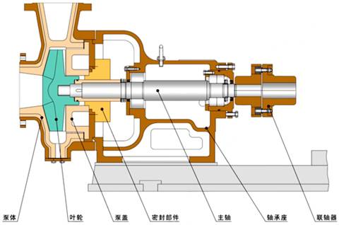
6, Structural type
7, Detailed parameters
|
Model \ Parameter |
At a speed of 1450 rpm |
At a speed of 2900 rpm |
Efficiencyη % |
||||||||||||
|
|
Flow rate Q (m3/h) |
Range H (m) |
Motor Power N (kW) |
Cavitation Surplus (m) |
Flow rate Q (m3/h) |
Range H (m) |
Motor Power N (kW) |
Cavitation Surplus (m) |
Weight (kg) |
|
|||||
|
HTB50-32-125 |
3.75 |
5.5 |
0.55 |
4.0 |
7.5 |
22 |
2.2 |
4.0 |
70 |
40 |
|||||
|
|
6.3 |
5.0 |
|
|
12.5 |
20 |
|
|
|
|
|||||
|
|
7.5 |
4.5 |
|
|
15.0 |
18 |
|
|
|
|
|||||
|
HTB50-32-160 |
3.75 |
8.75 |
0.75 |
4.5 |
7.5 |
35 |
4.0 |
4.5 |
90 |
35 |
|||||
|
|
6.3 |
8.0 |
|
|
12.5 |
32 |
|
|
|
|
|||||
|
|
7.5 |
7.0 |
|
|
15.0 |
30 |
|
|
|
|
|||||
|
HTB50-32-200 |
3.75 |
12.9 |
1.5 |
4.5 |
7.5 |
51.8 |
7.5 |
4.5 |
270 |
34 |
|||||
|
|
6.2 |
12.5 |
|
|
12.5 |
50 |
|
|
|
|
|||||
|
|
7.5 |
12 |
|
|
15.0 |
48 |
|
|
|
|
|||||
|
HTB65-50-160 |
7.5 |
8.88 |
0.75 |
4.5 |
15 |
35.5 |
5.5 |
4.5 |
110 |
52 |
|||||
|
|
12.5 |
8.0 |
|
|
25 |
32 |
|
|
|
|
|||||
|
|
15.0 |
7.0 |
|
|
30 |
29 |
|
|
|
|
|||||
|
HTB65-40-200 |
7.5 |
13.3 |
1.1 |
5.0 |
15 |
52 |
15 |
5.0 |
250 |
40 |
|||||
|
|
12.5 |
12.5 |
|
|
25 |
50 |
|
|
|
|
|||||
|
|
15 |
12 |
|
|
30 |
48 |
|
|
|
|
|||||
|
HTB80-65-160 |
15 |
8.75 |
1.5 |
4.5 |
30 |
35 |
11 |
4.5 |
120 |
58 |
|||||
|
|
25 |
8 |
|
|
50 |
32 |
|
|
|
|
|||||
|
|
30 |
7.13 |
|
|
60 |
29 |
|
|
|
|
|||||
|
HTB80-50-200 |
15 |
14 |
2.2 |
5.2 |
30 |
57 |
22 |
5.2 |
310 |
52 |
|||||
|
|
25 |
12.5 |
|
|
50 |
50 |
|
|
|
|
|||||
|
|
30 |
11.5 |
|
|
60 |
46 |
|
|
|
|
|||||
|
Model \ Parameter |
At a speed of 1450 rpm |
Efficiencyη % |
|||||||||||||
|
|
Flow rate Q (m3/h) |
Range H (m) |
Motor power N (kW) |
NPSH (m) |
Weight (kg) |
|
|||||||||
|
HTB125-100-315 |
60 |
37 |
22 |
5.5 |
730 |
54 |
|||||||||
|
|
100 |
32 |
|
|
|
|
|||||||||
|
|
120 |
48 |
|
|
|
|
|||||||||
|
HTB150-125-315 |
120 |
38 |
37 |
5.5 |
750 |
65 |
|||||||||
|
|
200 |
32 |
|
|
|
|
|||||||||
|
|
240 |
28 |
|
|
|
|
|||||||||
|
HTB200-150-315 |
280 |
35 |
55 |
5.5 |
760 |
68 |
|||||||||
|
|
315 |
32 |
|
|
|
|
|||||||||
|
|
360 |
30 |
|
|
|
|
|||||||||
|
HTB200-150-400 |
320 |
54 |
110 |
5.5 |
1600 |
66 |
|||||||||
8, Installation and Operation Instructions
Moving and Installation
1, When moving, the pump base should be the lifting force point to avoid vibration and impact.
2, Ceramic is a brittle material, and during disassembly and assembly, it should be avoided to knock and impact, and the parts should be handled with care. The pipeline and pump should be connected smoothly, and the ceramic plane of the pump should be padded with a soft bed, and it is not allowed to use a crowbar or bolts to forcibly align and tighten. The connecting bolts should not be too long, in order to make the contact surface of the parts to receive uniform pressure, please alternate the bolts along the diagonal direction. In addition, please do not tighten to the specified torque at one time, but at least 3 times slowly tighten, and the tightening should be uniform and not too tight, it is better not to leak.
3, The foundation for the installation of the entire set of pumps must be solid and have sufficient strength, the foundation surface is very flat, allowing a tolerance of ±Imm, and the anchor bolts are used for secondary grouting, so it is necessary to reserve appropriate grooves and holes on the installation foundation, and the anchor bolts can be adjusted for levelness with shims before the secondary grouting, and its levelness should not exceed 0.2/1000mm.
4, During the transportation and installation of the unit, the bolts may loosen and have relative displacement, so it is necessary to re-correct once after the unit is in place, and re-adjust the motor and pump head, and the coaxiality should be ensured between the two rotors: check the end face clearance between the two rotors, the end face clearance can be checked with a straight ruler or other instruments, the measurement of the left, right, up and down deviation of the two rotors should not exceed 0.15mm, and the difference between the maximum and minimum clearance of the two end faces should not exceed 0.15mm. After the adjustment is completed, the pump and motor anchor bolts should be tightened again, and it is necessary to check whether all the connecting bolts are loose.
5, The pump inlet should be lower than the liquid source surface and as close to the liquid source as possible. When the pump installation position is higher than the liquid surface (within the allowable suction lift of the pump), a bottom valve should be installed at the end of the suction pipe, and a liquid-filling hole or valve should be set on the discharge pipe for filling the pump before starting.
6, The suction pipeline and the discharge pipeline of the pump should have their own supports, and elastic joints should be installed at the inlet and outlet, and it is not allowed for the weight of the pipeline to be directly borne by the pump to avoid crushing the pump.
7, The inlet diameter of the pipeline should not be less than the pump inlet diameter, and the outlet diameter of the pipeline should not be greater than the pump outlet diameter. The inlet pipeline should be horizontal and free of arching to ensure that air is purged during filling.
8, During installation, do not allow screws, nuts, washers, slag, etc., to fall into the pipeline or pump, to avoid malfunctions.
9, According to the pump nameplate, if the date of manufacture to the time of use exceeds three months, for safety reasons, the pump cover should be removed first, and the impeller nut and shaft nut should be re-tightened with a special wrench, with a tightening force equivalent to 45-50Nm of torque wrench (the larger value for large pumps, and the opposite direction of the pump rotation for the shaft end thread).
Installation and Use
1, Starting:
a) A straight pipe should be installed at the pump outlet, and it is strictly prohibited to directly install a bend pipe; and a flow control valve should be placed, which should be closed before parking and opened in time after starting.
b) The ceramic parts of the ceramic pump may be damaged by thermal stress, so please avoid operation accompanied by sudden heating or cooling. If used under conditions exceeding the following sudden heating, sudden cooling limits, it will cause damage to the parts due to thermal shock.
Sudden heating temperature difference limit: When high-temperature liquid is introduced into the pump during shoulder (when the liquid circulation of the reboiler starts, etc.) 60℃.
Sudden cooling temperature difference limit: After transporting high-temperature liquid, immediately switch to low-temperature liquid operation (system sudden cooling operation, etc.) 40℃.
When the temperature difference exceeds the above, the temperature should be increased or decreased at a rate of 2℃ per minute.
c) For the first start, pay attention to the direction, and it is strictly prohibited to reverse. When checking the motor direction, do not connect the coupling, otherwise, it will damage the impeller, and it is necessary to ensure
that the direction is correct before connecting the coupling.
d) Before starting the pump, add lubricating oil to the bearing housing of the pump to the level center position of the oil gauge, to prevent the bearings from overheating. When the pump is running, pay attention to the regular加油 of the bearing housing. The first oil change is at 300 hours, and then every 3000 hours.
e) Turn the coupling by hand to check that the concentricity deviation of the main and electric couplings is less than 0.3mm, it should feel easy and uniform, and pay attention to whether there is any friction sound and foreign objects rolling in the pump. If there is, it should be eliminated, and the protective cover of the coupling should be installed.
f) Open the inlet valve to fill the pump with the conveying liquid. If the installation position of the pump is higher than the liquid surface, it is necessary to fill the pump or vacuum before starting, so that the pump and the suction pipe are filled with liquid and the air is purged.
g) For pumps with a cooling water device for the shaft seal, connect the cooling water before starting the pump, manually rotate the electric motor to make the pump run, and open the outlet valve at the same time.
h) In the case where the liquid level in the liquid source is lower than the center line of the pump's inlet, if the pump cannot be started normally due to the wear of the oil seal lip, the last oil seal at the shaft seal can be installed in reverse (i.e., the lip faces backward) to prevent air from entering the pump at the shaft seal and ensure the normal operation of the pump.
2, Operation:
a) It is necessary to regularly check the temperature rise of the pump and the electric motor, the temperature rise of the bearings should not be greater than 50℃, and its maximum temperature should not exceed 80℃.
b) Pay attention to the changes in the oil level in the bearing housing, often control it within the specified range, in order to keep the oil clean and well lubricated, it is necessary to regularly change the lubricating oil.
c) During the operation, if any abnormal sound or other faults are found, the pump should be stopped immediately for inspection, and the pump can be continued to operate only after the fault is eliminated.
d) It is absolutely not allowed to adjust the flow rate with the valve on the suction pipe, so as not to cause cavitation.
e) When the installation head of the pump is less than the rated head of the pump, the outlet valve must be closed to make the flow reach the rated value, if the outlet valve is fully open, the flow will be greater than the rated value, the motor may exceed the power, and the service life of the pump will be affected, the pump should not be continuously operated at a flow rate less than 30% and greater than 20% of the design flow rate.
f) Operation of the pump with the discharge valve closed is called closed-head operation, and the closed-head operation time should be kept as short as possible, with a limit of no more than 4 minutes for normal temperature media and no more than 1 minute for high-temperature media.
3, Pump shutdown:
a) Close the discharge valve, then stop the motor.
b) Close the suction valve.
c) Stop the supply of cooling water to the shaft seal.
d) If the ambient temperature is below 0℃, the pump should be drained of liquid after shutdown to prevent freezing; when transporting liquids that quickly solidify or mortar that is prone to settling, the pump should also be drained of liquid after shutdown to prevent faults on the next start-up.
Instructions for Mechanical Seal Use
1, Y2, Y4 type pumps can be used with mechanical seals for media with suspended particles, and the dynamic and static rings of this mechanical seal are both made of silicon carbide ceramic.
2, When disassembling the mechanical seal, it should be done carefully, and it is not allowed to use hammers, iron tools, etc., to avoid damaging the sealing surfaces of the dynamic and static rings. When installing, all sealing components should be checked for damage, and if any are found, they should be repaired or replaced.
3, In assembly, it is necessary to eliminate deviations, and the screws should be tightened evenly to avoid causing a tilt that would make the seal fail.
4, The compression of the spring should be adjusted correctly so that there is no leakage at the shaft seal. Do not compress the spring too much, otherwise, the dynamic and static rings may be burned.
5, Before starting the pump for a trial run, it is necessary to turn the pump by hand to check for any abnormal sounds, and the pump can be started only after it has been turned.
6, Close the discharge valve first, then stop the pump, and finally close the suction valve. Because after stopping the pump, the suction and discharge valves are not closed, the mechanical seal is in a pressurized state for a long time, and the spring is prone to lose its elasticity after a long time, which can cause foreign matter to enter between the dynamic and static rings, and the mechanical seal will be damaged and leak again when starting the pump next time.
7, For positions with precipitate crystallization, it is required to turn the coupling once when starting the pump to prevent the impeller or mechanical seal static and dynamic rings from being stuck by crystalline substances in case of forced startup, causing unnecessary damage. It is also possible to connect a water pipe for flushing before starting the pump.
8, Y4 mechanical seal must be connected to clean cooling water, tap water is fine, and the pump is strictly prohibited to operate without cooling water.
9, Notes for Y3 mechanical seal:
①Perform a static pressure test to determine that there is no leakage in static pressure, then connect the flushing connection pipe and other equipment.
②Pre-filled the pump and mechanical seal cavity with liquid.
③It is strictly prohibited to start the pump without filling the gap between the impeller and the pump body with slurry or without turning on the flushing water in the pump cavity. The air accumulated around the mechanical seal will cause the mechanical seal to dry run, causing damage.
④The mechanical seal cannot withstand the low-pressure environment when the pump direction is incorrect.
⑤When starting the pump, the flushing water must be turned on in advance and the pipeline must be checked to ensure that the flushing water in the seal cavity has a certain pressure before starting the pump.
. When stopping the pump, the pump must be turned off first, and then the flushing water is turned off.
⑥To ensure that the mechanical seal operates without failure, the flushing water pressure is greater than the medium pressure by 0.1~0.2Mpa during normal operation. The flow rate is 3-15L/min.
⑦It is necessary to reliably prevent any situation that exceeds the specified pressure range, such as: pressure fluctuations caused by pipeline vibration, etc.
⑧Statement: It is forbidden to operate without water in the seal cavity.
Any damage caused by dry running is not covered by our company's warranty.
Disassembly and Assembly
1, Disassembly:
a. Loosen the connecting bolts between the pump body and the pump cover, remove the pump cover, and wash the inner cavity of the pump body with water.
b.Loosen the shaft nut and the screen nut, and remove the impeller.
c.Tighten the bolts connecting the pump body to the bearing housing and the pump body to the shaft seal cooling cover, and remove the pump body.
d.Remove the shaft seal assembly.
e.Drain the lubricating oil, remove the bearing housing, loosen the connecting bolts of the front and rear covers of the bearing, and remove the rear cover of the bearing, the rear bearing, and the main shaft together, and then remove the front bearing.
2, Assembly:
a.Clean and wipe the parts, and replace any that are cracked, worn, or hardened and deformed. (During equipment maintenance, all auxiliary seal pad beds should be replaced.
b.During the installation of the mechanical seal, it should be kept clean. After installing the static ring, apply a layer of clean engine oil or transparent oil to its surface to reduce the friction resistance at startup. Correctly adjust the compression amount of the mechanical seal to avoid pressing it too tightly or too loosely. Generally, adjust the compression to the installation line.
c.Assemble in the reverse order of the pump disassembly.
d.Adjust the clearance.
9, Pump external dimensions and installation dimensions
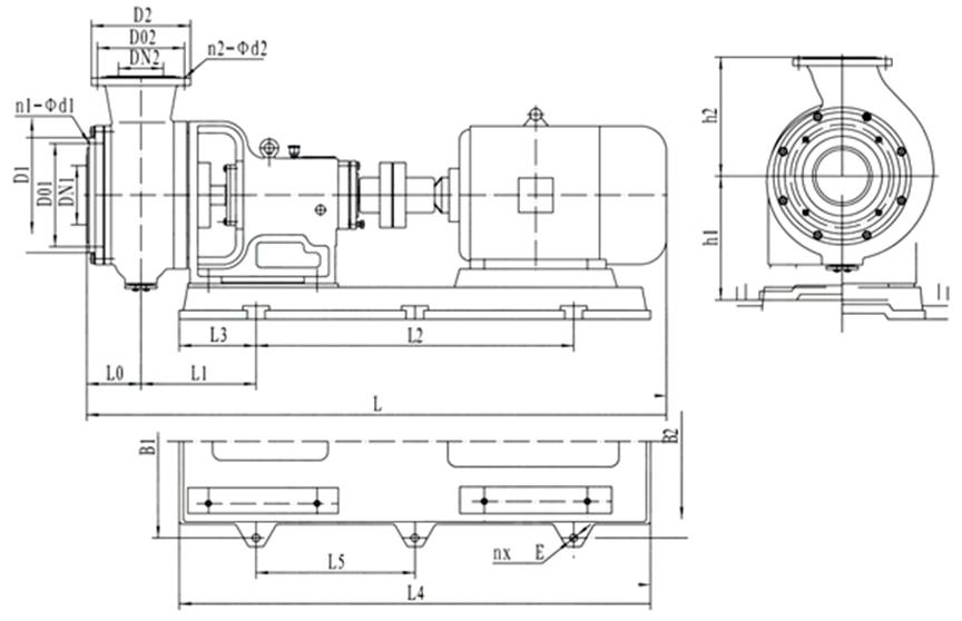
Mounting external dimensions table
Model |
Power (kW) |
With motor |
Installation dimensions | |||||||||||||||||||
| L | L0 | L1 | L2 | L3 | L4 | B1 | B2 | h1 | h2 | L5 | DN1 | D01 | D1 | n1-φd1 | DN2 | D02 | D2 | n2-φd2 | n-φE | |||
| HTB50-32-125 | 2.2 | Y90L-2 | 830 | 80 | 160 | 460 | 100 | 660 | 300 | 300 | 220 | 145 | 0 | 50 | 125 | 160 | 4-M16 | 32 | 100 | 135 | 4-M16 | 4-φ20 |
| 3 | Y100L-2 | 875 | ||||||||||||||||||||
| HTB50-32-160 | 4 | Y112M-2 | 995 | 90 | 240 | 455 | 180 | 815 | 354 | 354 | 265 | 170 | 0 | 50 | 125 | 160 | 4-M16 | 32 | 110 | 145 | 4-M16 | 4-φ20 |
| 5.5 | Y132S1-2 | 1070 | ||||||||||||||||||||
| HTB65-50-160 | 5.5 | Y132S1-2 | 1070 | 90 | 240 | 455 | 180 | 815 | 354 | 354 | 265 | 180 | 0 | 65 | 145 | 180 | 4-M16 | 50 | 125 | 160 | 4-M16 | 4-φ20 |
| 7.5 | Y132S2-2 | |||||||||||||||||||||
| HTB80-65-160 | 11 | Y160M1-2 | 1205 | 100 | 250 | 520 | 180 | 880 | 390 | 390 | 265 | 180 | 0 | 80 | 160 | 195 | 4-M16 | 65 | 145 | 180 | 4-M16 | 4-φ20 |
| 15 | Y160M2-2 | |||||||||||||||||||||
| HTB50-32-200 | 7.5 | Y132S2-2 | 1201 | 94 | 253 | 600 | 180 | 975 | 400 | 355 | 290 | 190 | 0 | 50 | 145 | 180 | 4-M16 | 32 | 125 | 160 | 4-M16 | 4-φ20 |
| HTB65-40-200 | 15 | Y160M2-2 | 1341 | 96 | 350 | 640 | 230 | 1100 | 400 | 400 | 290 | 210 | 0 | 65 | 160 | 195 | 4-M16 | 40 | 125 | 160 | 4-M16 | 4-φ20 |
| 18.5 | Y160L-2 | 1386 | ||||||||||||||||||||
| HTB80-50-200 | 22 | Y180M-2 | 1415 | 100 | 247 | 755 | 185 | 1125 | 460 | 460 | 300 | 220 | 0 | 80 | 160 | 195 | 4-M16 | 50 | 145 | 180 | 4-M16 | 4-φ20 |
| HTB125-100-315 | 22 | Y180L-4 | 1710 | 150 | 350 | 870 | 250 | 1370 | 610 | 610 | 420 | 355 | 0 | 125 | 240 | 280 | 8-M20 | 100 | 240 | 280 | 8-M20 | 4-φ26 |
| 30 | Y200L-4 | 1775 | ||||||||||||||||||||
| HTB150-125-315 | 37 | Y225S-4 | 1835 | 160 | 388 | 905 | 260 | 1425 | 610 | 610 | 420 | 365 | 0 | 150 | 270 | 310 | 8-M20 | 125 | 240 | 280 | 8-M20 | 4-φ26 |
| 45 | Y225M-4 | 1860 | ||||||||||||||||||||
| HTB200-150-315 | 55 | Y250M-4 | 1965 | 179 | 414 | 990 | 280 | 1550 | 655 | 655 | 420 | 400 | 0 | 200 | 350 | 390 | 8-M20 | 150 | 295 | 335 | 8-M20 | 4-φ26 |
| HTB200-150-400 | 110 | Y315S-4 | 2630 | 200 | 125 | 1800 | 260 | 2400 | 850 | 850 | 560 | 450 | 900 | 200 | 350 | 390 | 12-M20 | 150 | 295 | 335 | 8-M20 | 6-φ28 |