
1. Product Description
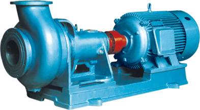
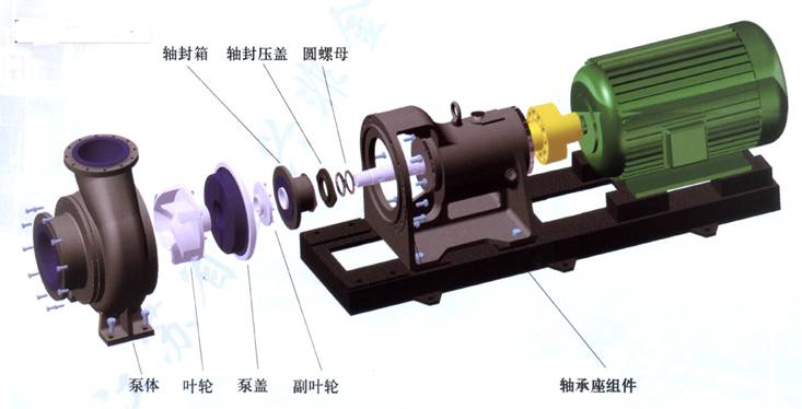
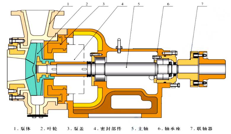
HTB series corrosion-resistant engineering plastic pump is a single-stage single-suction cantilever centrifugal pump. The flow-through components are generally made of steel-lined ultra-high molecular weight polyethylene (UHMWPE). Its outstanding advantages are its excellent wear resistance, impact resistance (especially low temperature impact resistance), creep resistance (enhanced environmental stress cracking) and good corrosion resistance in all plastics, and it has broad application fields. The pump structure refers to the ISO2858 standard and adopts the internationally popular back cover adjustable bearing frame. The bearing spacing is long, the cantilever is short, the shaft diameter is thick, the operation is stable, reliable, no dry sound, thin oil lubrication cooling, advanced structure and more effect. The work efficiency is 5% to 8% higher than domestic old models and it has compact structure, convenient maintenance, no need to dismantle the inlet and outlet pipes for maintenance. The pump also has a high degree of generalization.
2.Characteristics
Seal: mechanical seal, packing seal, oil seal seal, dynamic seal.Applicable medium: sulfuric acid with a concentration of 75% or less, nitric acid with a concentration of 50% or less, hydrochloric acid of various concentrations, and liquid alkali. It is suitable for both clear liquid and slurry.
The main technical parameters: the use temperature -20 ° C ~ 90 ° C (for special requirements, the use of other materials, can be increased to 120 ° C), the inlet diameter of 50mm ~ 700mm, the flow rate of 5 ~ 4800m3 / h, the lift within 80m.
3. Application Fields
●Various corrosive pulps in the smelting industry; dilute acid, mother liquor, sewage, seawater, fluorosilicic acid containing silica gel, phosphoric acid slurry;
●Non-ferrous metal smelting industry: suitable for various acid liquids such as lead, zinc, gold, silver, copper, manganese, cobalt, rare earth, etc., corrosive pulp, slurry (for filter press) electrolyte, sewage Such as medium transport.
●Chemical and other enterprises: various clear or slurry positions of sulfuric acid, hydrochloric acid, alkaline and oil. Titanium dioxide, iron red powder production, various dyes, pigment production, non-metallic mineral processing and other industries.
●Chlorine alkali Industry: hydrochloric acid, liquid alkali, electrolyte, etc.
●Water treatment industry: pure water, high purity water, sewage.
●Steel companies: sulfuric acid and hydrochloric acid posts in pickling systems, sewage with impurities.
●Wet desulfurization circulating pump: It can be used in alkaline, acidic and corrosive situations at the same time.
4.Model Description
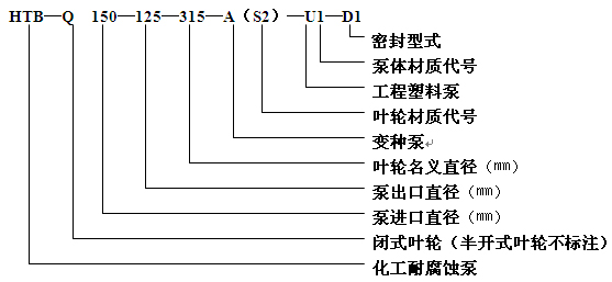
Codes of impeller materials
Materials | UHMWPE | Modified rubber | Fluoro-plastic alloy | PVDF | Chlorinated polyether | Stainless Steel | ||
Anticorrosive & wear-resisting | Heat-resisting & wear-resisting | Anticorrosive | ||||||
Code | S | S1 | S3 | S2 | S4 | S5 | S6 | G |
Note | not for U type pump | |||||||
Codes of pump materials
| Materials | UHMWPE | Modified rubber | Fluoro-plastic alloy | PVDF | Chlorinated polyether | Stainless Steel | ||
Anticorrosive & wear-resisting | Heat-resisting & wear-resisting | Anticorrosive | ||||||
Code | U | U1 | U3 | U 2 | U 4 | U 5 | U 6 | G |
Note | ||||||||
Seal type | Oil seal | Packing seal | Mechanical seal | Dynamic seal of Auxiliary impeller | ||||||
WB2 | Hard to hard seal | Double End seal | Centralized | Packing seal | Oil seal | Oil seal | Mechanical seal | |||
Code | Y1 | T | J | Y2 | Y3 | Y4 | D | D1 | D2 | D3 |
Note | cooling water | with clear liquid pump | cooling water | cooling water | cooling water | cooling water | without cooling water | cooling water | ||
Structure type
Type of shaft seal


Parameter details
Parameters \ Model | Specification of impeller | Rated Rev. 2900 r/Min. | Rated Rev. 1450 r/Min. | NPSH | Weight | ||||||
Flow Q | Lift H | Power of motor N Specific gravity of media | Efficiency η | Flow Q | Lift | Power of motor N Specific gravity of media | Efficiency η | ||||
HTB50 | Standard | 7.5 | 22 | 2.2 | 40 | 3.75 | 5.5 | 0.55 | 35 | 4.0 | 90 |
12.5 | 20 | 6.3 | 5.0 | ||||||||
15.0 | 18 | 7.5 | 4.5 | ||||||||
A | 5 | 20 | 2.2 | 27 | |||||||
10 | 15 | 2.2 | 29 | ||||||||
B | 7.5 | 16 | 1.5 | 28 | |||||||
C | 15 | 15 | 2.2 | 36 | |||||||
10 | 18 | 2.2 | 34 | ||||||||
HTB50 | Standard | 7.5 | 35 | 4.0 | 35 | 3.75 | 8.75 | 0.75 | 30 | 4.5 | 145 |
12.5 | 32 | 6.3 | 8.0 | ||||||||
15.0 | 30 | 7.5 | 7.0 | ||||||||
A | 10 | 25 | 4.0 | 35 | |||||||
15 | 23.5 | 4.0 | 36 | ||||||||
B | 16.5 | 25 | 4.0 | 38 | |||||||
20 | 22 | 4.0 | 39 | ||||||||
C | 25 | 20 | 5.5 | 38 | |||||||
HTB50 | Standard | 7.5 | 51.8 | 7.5 | 34 | 3.75 | 12.9 | 1.5 | 28 | 4.5 | 270 |
12.5 | 50 | 6.2 | 12.5 | ||||||||
15.0 | 48 | 7.5 | 12 | ||||||||
A | 5 | 48 | 7.5 | 20 | |||||||
B | 12 | 57 | 11 | 25 | |||||||
16 | 54 | 11 | 27 | ||||||||
C | 17.5 | 41 | 7.5 | 30 | |||||||
HTB50 | Standard | 7.8 | 83.1 | 15 | 27 | 3.9 | 20.8 | 3.0 | 20 | 4.5 | 330 |
12.5 | 80 | 6.3 | 20 | ||||||||
15 | 79 | 7.5 | 19.8 | ||||||||
A | 20 | 60 | 15 | 30 | |||||||
26 | 55.6 | 15 | 33 | ||||||||
B | 17 | 83 | 18.5 | 29 | |||||||
23 | 80 | 18.5 | 34 | ||||||||
C | 25 | 70 | 18.5 | 31 | |||||||
HTB65 | Standard | 15 | 35.5 | 5.5 | 52 | 7.5 | 8.8 | 0.75 | 47 | 4.5 | 150 |
25 | 32 | 12.5 | 8.0 | ||||||||
30 | 29 | 15.0 | 7.0 | ||||||||
A | 20 | 28 | 5.5 | 45 | |||||||
25 | 25 | 50 | |||||||||
B | 40 | 20 | 52 | ||||||||
HTB65 | Standard | 15 | 52 | 15 | 40 | 7.5 | 13.3 | 1.1 | 35 | 5.0 | 250 |
25 | 50 | 12.5 | 12.5 | ||||||||
30 | 48 | 15 | 12 | ||||||||
A | 15 | 41 | 11 | 33.4 | |||||||
20 | 40 | 34 | |||||||||
27 | 39 | 45 | |||||||||
B | 25 | 40 | 40 | ||||||||
C | 20 | 40 | 31 | ||||||||
30 | 35 | 36 | |||||||||
HTB80 | Standard | 30 | 35 | 11 | 58 | 15 | 8.75 | 1.5 | 54 | 4.5 | 170 |
50 | 32 | 25 | 8 | ||||||||
60 | 29 | 30 | 7.13 | ||||||||
A | 40 | 28 | 7.5 | 58 | |||||||
B | 60 | 25 | 11 | 48 | |||||||
C | 52 | 22 | 7.5 | 57 | |||||||
65 | 18 | 11 | 54 | ||||||||
75 | 15 | 11 | 50 | ||||||||
HTB80 | Standard | 30 | 57 | 22 | 52 | 15 | 14 | 2.2 | 48 | 5.2 | 310 |
50 | 50 | 25 | 12.5 | ||||||||
60 | 46 | 30 | 11.5 | ||||||||
A | 43 | 42.5 | 15 | 48 | |||||||
54 | 39 | 51 | |||||||||
60 | 36 | 49 | |||||||||
B | 42 | 51 | 18.5 | 49.5 | |||||||
58 | 47 | 55 | |||||||||
65 | 45 | 55.4 | |||||||||
C | 70 | 41.5 | 18.5 | 55 |
Parameters/Model | Specification of impeller | Rated Rev. 1450 r/Min. | NPSH | Weight (kg) | |||
Flow Q | Lift H | Power of motor N | Efficiency η | ||||
HTB80 | Standard | 15 | 32.6 | 11 | 35 | 5.2 | 610 |
25 | 32 | ||||||
32 | 30.9 | ||||||
HTB125 | Standard | 60 | 37 | 22 | 54 | 5.5 |
730 |
100 | 32 | ||||||
120 | 30 | ||||||
A | 80 | 30 | 18.5 | 51 | |||
B | 110 | 20 | 15 | 52 | |||
C | 140 | 34 | 30 | 58 | |||
HTB125 | Standard | 80 | 51 | 37 | 52 | 5.5 | 1000 |
100 | 50 | ||||||
120 | 48 | ||||||
A | 120 | 55 | 45 | 50 | |||
B | 150 | 48 | 45 | 50 | |||
C | 180 | 40 | 45 | 51 | |||
HTB150 | Standard | 120 | 38 | 37 | 65 | 5.5 | 750 |
200 | 32 | ||||||
240 | 28 | ||||||
A | 200 | 22 | 30 | 64 | |||
B | 220 | 25 | 30 | 65 | |||
C | 250 | 24 | 30 | 65 | |||
D | 200 | 36 | 37 | 65 | |||
HTB150 | Standard | 150 | 54 | 55 | 62 | 5.5 | 1020 |
200 | 50 | ||||||
240 | 45 | ||||||
A | 225 | 47 | 75 | 55 | |||
B | 200 | 42 | 55 | 56 | |||
C | 200 | 45 | 55 | 57 | |||
HTB200 | Standard | 280 | 35 | 55 | 68 | 5.5 | 760 |
315 | 32 | ||||||
360 | 30 | ||||||
A | 320 | 18 | 37 | 62 | |||
B | 350 | 24 | 45 | 64 | |||
C | 370 | 20 | 45 | 64 | |||
HTB200 | Standard | 310 | 43 | 75 | 68 | 5.5 | 1040 |
340 | 40 | ||||||
360 | 37 | ||||||
A | 315 | 38 | 75 | 62 | |||
B | 400 | 30 | 62 | ||||
C | 440 | 28 | 60 | ||||
HTB200 | Standard | 320 | 54 | 110 | 66 | 5.5 | 1600 |
400 | 50 | ||||||
440 | 48 | ||||||
A | 405 | 37 | 75 | 62 | |||
B | 370 | 40 | 90 | 61.5 | |||
C | 400 | 45 | 110 | 60 | |||
HTB250 | Standard | 400 | 45 | 132 | 68 | 5.5 | 1620 |
500 | 40 | ||||||
600 | 36 | ||||||
A | 480 | 48 | 60 | ||||
B | 700 | 28 | 60 | ||||
C | 520 | 42 | 61 | ||||
Parameters/Model | Specification of impeller | Rated Rev. 980 r/Min. | NPSH | Weight | |||
Flow Q | Lift H | Power of motor N | Efficiency η | ||||
HTB500 | Standard | 2300 | 53 | 450 | 82 | 8.0 | 5500 |
2500 | 50 | ||||||
2600 | 45 | ||||||
A | 1600 | 65 | 450 | 74 | |||
2300 | 60.5 | 560 | 80 | ||||
HTB450 | Standard | 1865 | 76.8 | 710 | 77 | 8.0 | 6500 |
2200 | 72 | ||||||
2650 | 67 | ||||||
HTB350 | Standard | 1500 | 18 | 132 | 62.5 | 6.0 | 2250 |
HTB500 | Standard | 2400 | 60.5 | 710 | 77 | 8.0 | 6600 |
3000 | 55 | ||||||
3300 | 51.8 | ||||||
Parameters/Model | Specification of impeller | Rated Rev. 740 r/Min. | NPSH | Weight | |||
Flow Q | Lift H | Power of motor N | Efficiency η | ||||
HTB500 | Standard | 1890 | 32.8 | 280 | 71 | 8.0 | 5500 |
2200 | 26.6 | ||||||
2340 | 23.6 | ||||||
HTB700 | Standard | 2750 | 63 | 710 | 84 | 5.0 | 6750 |
3290 | 60 | ||||||
3600 | 54 | ||||||
HTB600-600-700 | Standard | 4800 | 24 | 450 | 82 | 6.0 | |
HTB300 | Standard | 860 | 33 | 160 | 72 | 6.0 | 2200 |
1000 | 32 | ||||||
1180 | 31 | ||||||
A | 1440 | 30 | 200 | 63 | |||
B | 1200 | 25 | 160 | 62 | |||
C | 960 | 22 | 110 | 60 | |||
750 | 26 | 110 | 60 | ||||
D | 960 | 36 | 200 | 63 | |||
HTB300 | Standard | 850 | 51 | 250 | 70 | 6.0 | 2240 |
1000 | 50 | ||||||
1100 | 48.8 | ||||||
A | 600 | 45 | 160 | 60 | |||
B | 750 | 50 | 200 | 60 | |||
C | 1200 | 45 | 250 | 68 | |||
D | 1440 | 40 | 250 | 68 | |||
HTB300 | Standard | 1300 | 59.6 | 355 | 67.5 | 8.0 | 2500 |
1400 | 58 | 355 | 69 | ||||
1500 | 55 | 355 | 70 | ||||
1600 | 53 | 400 | 70 | ||||
A | 600 | 55 | 250 | 56 | |||
B | 800 | 55 | 250 | 57 | |||
C | 1400 | 45 | 315 | 65 | |||
D | |||||||
E | 1440 | 60 | 400 | 70 | |||
HTB100 | Standard | 33 | 32.9 | 15 | 40 | 5.2 | 620 |
50 | 32 | ||||||
75 | 29.7 |
X.Instructions for Installation, Use and Maintenance
X.1 Handing and Installation
10.1.1 When transported, the pump base should be used as the lifting part to avoid vibration and impact.
10.1.2 The foundation for installing the complete pump must be strong and have sufficient strength. The base surface is very flat and the tolerance is ±1mm. The anchor bolts are filled with secondary grouting. Therefore, appropriate grooves and perforations should be reserved on the basis of installation. Before the secondary grouting, the level of the unit can be adjusted with the horn, and the horizontal tolerance is 0.2/1000 mm.
10.1.3 During the transportation and installation process, the unit may cause loose bolts and relative displacement, so the unit should be recalibrated once after the unit is placed. Re-adjust the motor and pump head, and ensure concentricity between the couplings: Check the end face clearance between the couplings. The outer circle concentricity can be checked with a ruler or other instrument. The upper and lower left and right misalignment of the coupling should not exceed 0.15mm. The maximum and minimum clearance difference between the two coupling end face clearances no more than 0.15mm in one week. After the adjustment is completed, tighten the anchor bolts of the pump and motor and check if all the coupling bolts are loose.
10.1.4 The pump inlet should be lower than the source side and as close as possible to the source. When the pump is installed above the liquid level (within the suction range of the pump), a bottom valve should be installed at the end of the suction pipe, and a liquid screw hole or valve should be provided on the discharge pipe for the pump before use.
10.1.5 The suction and extrusion lines of the pump shall have their own brackets. The inlet and outlet shall be fitted with elastic joints. The weight of the pipeline shall not be directly absorbed by the pump to avoid crushing the pump.
10.1.6 The inlet diameter of the pipeline should not be smaller than the diameter of the pump inlet. The diameter of the outlet of the pipeline should not be larger than the diameter of the pump outlet. The inlet pipeline should be horizontal without buckling to ensure that the air is drained during the filling.
10.1.7 To avoid malfunction, do not allow screws, nuts, washers, welding slag, etc. to fall into the pipeline or pump during installation.
X.2 Installation and Use
X.2.1 Start up
a. The pump outlet should be installed with a straight pipe. It is strictly forbidden to install the elbow directly. The flow regulating valve should be installed and be closed before parking. The valve should be opened in time after driving.
b. When driving for the first time, pay attention to steering. From the motor to the pump casing, turn to clockwise rotation. Reverse rotation is strictly prohibited. When checking the motor steering, do not connect the coupling, otherwise the impeller should be damaged. Make sure that the steering is correct before connecting the coupling.
c. Before driving, inject lubricant into the bearing housing of the pump to the horizontal center position of the oil mark to avoid overheating of the bearing. When the pump is running, pay attention to the regular lubrication of the bearing housing. The lubricating oil should be N46 mechanical oil. Change the oil for the first time for 300 hours, and replace it every 3,000 hours later.
d. Move the coupling with the hand and check that the main and electrical concentricity deviation is less than 0.3mm. It should be easy and light and uniform, and pay attention to the noise in the pump such as friction and foreign matter rolling. If so, try to remove it and install the shield of the coupling.
e. Open the inlet valve and fill the pump with the transfer fluid. If the installation position of the pump is higher than the liquid level, pump or vacuum before starting, so that the pump and the suction tube are filled with liquid and the air is drained.
f. The shaft is sealed with a cooling water device. Before driving, the cooling water is turned on, the motor is started to operate the pump, and the outlet valve is opened. When the pump is running normally, it can continue to be connected. If the conditions are not allowed, it can be stopped. There is no requirements for the flow and pressure of the cooling water, so that the tap water can be used.
X.2.2 Operation
a. Often check the temperature rise of the pump and motor. The temperature rise of the bearing should not exceed 50 °C, and the limit temperature should not exceed 80 °C.
b. Pay attention to the change of oil level in the bearing housing, which is often controlled within the specified range. In order to keep the oil clean and well lubricated, the lubricating oil should be replaced regularly.
c. During the operation, if there is abnormal sound or other malfunction, stop the pump immediately and wait until the fault is removed before continuing operation.
d. To avoid cavitation, never use a valve on the suction line to regulate the flow.
e. When the pump head of the pump is less than the rated head of the pump, the small outlet valve must be closed to achieve the flow rate. If the outlet valve is fully open, the flow will be greater than the rated value, the motor may be overpowered, which will affect the life of the pump.
f. The operation of the pump when the outlet valve is closed is called the closed-pressure operation state. Keep the closing operation time of the all-plastic pump or the plastic-lined pump as short as possible. The medium temperature medium is limited to not more than 5 minutes, and the high temperature medium is preferably not more than 2 minutes.
X.2.3 Stop
a. Close the outlet valve and stop the motor.
b. Close the inlet valve.
c. Stop supplying cooling water at the shaft seal.
d. When the ambient temperature is lower than 0 °C, the liquid in the pump should be drained after stopping the pump to prevent freezing. When conveying a fast-solidifying liquid or a mortar that is easy to precipitate, the liquid in the pump should also be drained after stopping the pump to avoid malfunction at the next startup.
e.
f. When transporting medium that is easy to crystallize, solidify, precipitate and etc, after stopping the pump, it should prevent clogging in time. flush the pump and pipeline with clean water or other medium to rinse sealed chambers.
X.3 Precautions while using Mechanical Seal
10.3.1 Mechanical seals are suitable for clean, non-suspended media. The newly installed piping system and liquid storage tank should be carefully cleaned to prevent solid impurities from entering the mechanical seal end face and causing the seal to fail.
10.3.2 Be careful when disassembling the mechanical seal. It is not allowed to strike with a hammer or iron to avoid damaging the dynamic and static ring sealing surfaces. All seal components should be inspected for damage during installation and, if any, repaired or replaced.
10.3.3 Pay attention to eliminate the deviation during assembly, and tighten the screws evenly to avoid deflection and invalidize the seal.
10.3.4 Correctly adjust the compression of the spring so that the shaft seal does not leak. Do not compress the spring too much to avoid burning or static ring burning.
X.4 Disassembly and Assembly
X.4.1 Disassemble
a. Remove the drain hole pressure plate on the pump body and drain the liquid in the pump.
b. Remove the inlet takeover.
c. Remove the pump body.
d. Fix the coupling and turn it off in the opposite direction of the running direction.
e. For the packing sealing structure, the pump cover and the sleeve can be removed from the shaft first, then the sleeve is removed, and then the gland, packing and packing ring are removed in sequence.
f. For the mechanical seal structure, the pump cover can be removed together with the mechanical seal static ring, static ring gland and etc. Then the static ring gland is removed, and the static ring is taken out. The sleeve is then removed from the shaft together with the mechanical seal assembly, and the mechanical seal and sleeve are then disassembled.
g. For the dynamic sealing structure, the shaft sealing box can be separated from the pump cover by using the disassembly screw hole, the pump cover and the impeller are removed in turn, then the sleeve is removed, and the gland, the oil seal and the packing ring are sequentially removed.
h. Drain the lubricating oil, remove the bearing seat, loosen the coupling bolts of the front and rear side covers of the bearing, take out the bearing rear side cover, the rear bearing and the main shaft together, and then remove the front bearing.
X.4.2 Assembly
a. Clean all components. If they are cracked, worn or hardened, they should be replaced with new ones.
b. Assembly in the reverse order of pump removal.
c. The coupling bolts of the pump body and the bearing housing should not be tightened too tightly. It should be evenly stressed to avoid leak.
d. Adjust the gap.
X.5 Possible Failure and Elimination Methods
Failure | Cause | Elimination Method |
Can't get liquid
| 1. The motor is not turning right. | 1. Change the steering |
2. Air is left in the pump or in the suction pipe. | 2. Refill and remove air | |
3. Suction too high or insufficient perfusion | 3. Reduce the pump position and increase the pressure at the inlet | |
4. The suction line is too small or obstructed by debris | 4. Increase the suction pipe diameter and remove the blockage | |
5. The suction pipe is not deep enough or leaking | 5. Increase the immersion depth or repair pipeline | |
Insufficient traffic
| 1. The impeller is seriously corroded | 1. Replace the impeller |
2. The speed is insufficient | 2. Increase the speed | |
3. The gap between the impeller and the pump body is too large. | 3. Re-adjust the gap | |
4. The pressure outlet is partially blocked | 4. Remove the blocked part | |
Insufficient Lift
| 1. The liquid contained in the liquid contains gas | 1. Reduce liquid temperature to remove gas |
2. Impeller corrosion is serious | 2. Replace the impeller | |
3. The speed is insufficient | 3. Increase the speed | |
Power overload
| 1. The flow rate exceeds the scope of use | 1. Operate according to the scope of use of the pump |
2. The medium weight is too large | 2. Replace the larger power motor | |
3. Produce mechanical friction | 3. Check the friction and adjust or replace the worn parts. | |
Bearing heating
| 1. The pump shaft is different from the motor shaft | 1. Adjust the concentricity |
2. Oil shortage or oil deterioration in the bearing housing | 2. Refuel or change oil | |
Noise or vibration | 1. The pump shaft is different from the motor shaft | 1. Adjust the concentricity |
2. The liquid contained in the liquid contains gas | 2. Reduce liquid temperature to remove gas | |
3. Rotor imbalance | 3. Replacement parts | |
4. The nut is loose | 4. Tighten the nuts of each part | |
5. The pressure outlet is partially blocked | 5. Remove the blocked part | |
6. Bearing damage | 6. Replace the bearing |
XI. Shape and Installation Size of Pump
Installation External Dimensions Table
Model | Power | 配带 | 安 装 外 形 尺 寸 | |||||||||||||||||||
L | L0 | L1 | L2 | L3 | L4 | B1 | B2 | h1 | h2 | L5 | DN1 | D01 | D1 | n1-φd1 | DN2 | D02 | D2 | n2-φd2 | n-φE | |||
HTB50-32-125 | 2.2 | Y90L-2 | 830 | 80 | 160 | 460 | 100 | 660 | 300 | 300 | 220 | 145 | 0 | 50 | 125 | 160 | 4-M16 | 32 | 100 | 135 | 4-M16 | 4-φ20 |
3 | Y100L-2 | 875 | ||||||||||||||||||||
HTB50-32-160 | 4 | Y112M-2 | 995 | 90 | 240 | 455 | 180 | 815 | 354 | 354 | 265 | 170 | 0 | 50 | 125 | 160 | 4-M16 | 32 | 110 | 145 | 4-M16 | 4-φ20 |
5.5 | Y132S1-2 | 1070 | ||||||||||||||||||||
HTB65-50-160 | 5.5 | Y132S1-2 | 1070 | 90 | 240 | 455 | 180 | 815 | 354 | 354 | 265 | 180 | 0 | 65 | 145 | 180 | 4-M16 | 50 | 125 | 160 | 4-M16 | 4-φ20 |
7.5 | Y132S2-2 | |||||||||||||||||||||
HTB80-65-160 | 11 | Y160M1-2 | 1205 | 100 | 250 | 520 | 180 | 880 | 390 | 390 | 265 | 180 | 0 | 80 | 160 | 195 | 4-M16 | 65 | 145 | 180 | 4-M16 | 4-φ20 |
15 | Y160M2-2 | |||||||||||||||||||||
HTB50-32-200 | 7.5 | Y132S2-2 | 1201 | 94 | 253 | 600 | 180 | 975 | 400 | 355 | 290 | 190 | 0 | 50 | 145 | 180 | 4-M16 | 32 | 125 | 160 | 4-M16 | 4-φ20 |
HTB65-40-200 | 15 | Y160M2-2 | 1341 | 96 | 350 | 640 | 230 | 1100 | 400 | 400 | 290 | 210 | 0 | 65 | 160 | 195 | 4-M16 | 40 | 125 | 160 | 4-M16 | 4-φ20 |
18.5 | Y160L-2 | 1386 | ||||||||||||||||||||
HTB80-50-200 | 22 | Y180M-2 | 1415 | 100 | 247 | 755 | 185 | 1125 | 460 | 460 | 300 | 220 | 0 | 80 | 160 | 195 | 4-M16 | 50 | 145 | 180 | 4-M16 | 4-φ20 |
HTB50-32-250 | 18.5 | Y160L-2 | 1386 | 96 | 285 | 780 | 180 | 1120 | 460 | 460 | 310 | 225 | 0 | 50 | 145 | 180 | 4-M16 | 32 | 125 | 160 | 4-M16 | 4-φ20 |
HTB80-50-315 | 11 | Y160M-4 | 1748 | 300 | 365 | 870 | 250 | 1370 | 610 | 610 | 420 | 450 | 0 | 80 | 160 | 195 | 8-φ18 | 50 | 125 | 160 | 4-φ18 | 4-φ26 |
HTB125-100-315 | 22 | Y180L-4 | 1710 | 150 | 350 | 870 | 250 | 1370 | 610 | 610 | 420 | 355 | 0 | 125 | 240 | 280 | 8-M20 | 100 | 240 | 280 | 8-M20 | 4-φ26 |
30 | Y200L-4 | 1775 | ||||||||||||||||||||
HTB150-125-315 | 37 | Y225S-4 | 1835 | 160 | 388 | 905 | 260 | 1425 | 610 | 610 | 420 | 365 | 0 | 150 | 270 | 310 | 8-M20 | 125 | 240 | 280 | 8-M20 | 4-φ26 |
45 | Y225M-4 | 1860 | ||||||||||||||||||||
HTB200-150-315 | 55 | Y250M-4 | 1965 | 179 | 414 | 990 | 280 | 1550 | 655 | 655 | 420 | 400 | 0 | 200 | 350 | 390 | 8-M20 | 150 | 295 | 335 | 8-M20 | 4-φ26 |
HTB200-150-380 | 75 | Y280S-4 | 2010 | 160 | 180 | 1200 | 300 | 1830 | 670 | 670 | 475 | 450 | 600 | 200 | 310 | 360 | 12-M20 | 150 | 250 | 300 | 8-M20 | 6-φ20 |
HTB100-80-350 | 18.5 | Y160L-4 | 1755 | 282 | 361 | 870 | 250 | 1370 | 610 | 610 | 420 | 492 | 0 | 100 | 180 | 220 | 8-φ18 | 80 | 160 | 200 | 4-φ18 | 4-φ26 |
HTB125-100-400 | 45 | Y225M-4 | 1891 | 163 | 212 | 1050 | 360 | 1755 | 690 | 610 | 485 | 420 | 0 | 125 | 240 | 280 | 8-M20 | 100 | 240 | 280 | 8-M20 | 4-φ26 |
55 | Y250M-4 | 1936 | 163 | 197 | 1090 | 360 | 1812 | 690 | 690 | |||||||||||||
75 | Y280S-4 | 2001 | 163 | 168 | 1200 | 300 | 1830 | 670 | 670 | 475 | 420 | 600 | 6-φ20 | |||||||||
HTB150-125-400 | 55 | Y250M-4 | 1983 | 170 | 197 | 1090 | 360 | 1812 | 690 | 690 | 485 | 420 | 0 | 150 | 270 | 310 | 8-M20 | 125 | 240 | 280 | 8-M20 | 4-φ26 |
75 | Y280S-4 | 2053 | 170 | 180 | 1200 | 300 | 1830 | 670 | 670 | 475 | 420 | 600 | 150 | 270 | 310 | 8-M20 | 125 | 240 | 280 | 8-M20 | 6-φ20 | |
HTB200-150-400 | 110 | Y315S-4 | 2630 | 200 | 125 | 1800 | 300 | 2400 | 850 | 850 | 560 | 450 | 900 | 200 | 350 | 390 | 12-M20 | 150 | 295 | 335 | 8-M20 | 6-φ28 |
HTB250-200-400 | 132 | Y315M-4 | 2705 | 200 | 125 | 1800 | 300 | 2400 | 850 | 850 | 560 | 450 | 900 | 250 | 350 | 390 | 12-M20 | 200 | 295 | 335 | 8-M20 | 6-φ28 |
HTB300-250-400 | 160 | Y315L1-4 | 2877 | 350 | 57 | 1900 | 300 | 2500 | 850 | 850 | 580 | 580 | 950 | 300 | 460 | 500 | 12-M20 | 250 | 400 | 440 | 12-M20 | 6-φ35 |
Installation External Dimensions Table
型 号 | 功率 | 配带 | 安 装 外 形 尺 寸 | |||||||||||||||||||
L | L0 | L1 | L2 | L3 | L4 | B1 | B2 | h1 | h2 | L5 | DN1 | D01 | D1 | n1-φd1 | DN2 | D02 | D2 | n2-φd2 | n-φE | |||
HTB300-250-580 | 250 | Y355M-4 | 3120 | 355 | 271 | 1650 | 450 | 2580 | 850 | 850 | 620 | 580 | 825 | 300 | 460 | 500 | 12-M20 | 250 | 400 | 440 | 12-M20 | 6-φ35 |
HTB300-250-600 | 315 | Y355L-4 | 3250 | 350 | 270 | 1650 | 450 | 2580 | 850 | 850 | 620 | 650 | 825 | 300 | 460 | 500 | 12-M20 | 250 | 400 | 440 | 12-M20 | 6-φ35 |
355 | YKK4003-4 | 3537 | 350 | 270 | 2200 | 450 | 3225 | 850 | 970 | 620 | 650 | 1100 | 300 | 460 | 500 | 12-M20 | 250 | 400 | 440 | 12-M20 | 6-φ35 | |
HTB350-350-450 | 132 | Y315L2-6 | 2900 | 350 | 80.5 | 1900 | 300 | 2500 | 850 | 850 | 670 | 650 | 950 | 350 | 515 | 565 | 16-M20 | 350 | 515 | 565 | 16-M20 | 6-φ35 |